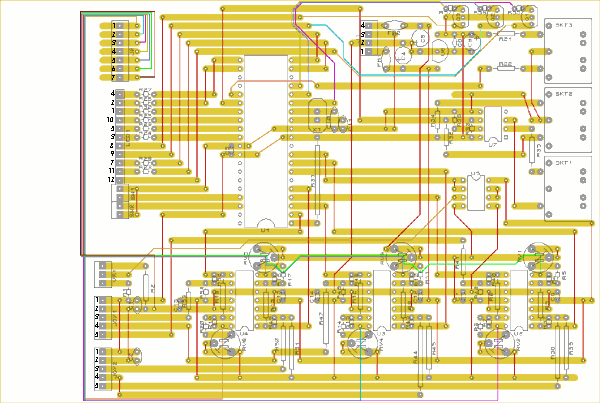
JoyKontrol - Stripboard layout

The BOOSTER sub-circuits (Q1, Q2, Q3, R55, R56, R57 on top right of the board) were a last minute addition so they are rather squeezed on. The left sides of R55, R56, R57 need to be soldered directly to the wire connections rather than into the board.
Note that the LED jumper pin numbers on the schematic do not correspond to the pin numbers of the LED unit itself - this was done to make the routing on the stripboard easier. However I have labelled the jumper pins correctly on the layout image above - the numbers on the image correspond to the actual pin numbers of the LED unit itself.
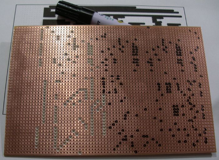
To use as a guide when breaking the stripboard tracks, save and print this TIFF file. This is an actual size view of the tracks from the copper strip side, and can be used as follows:
- Cut a piece of stripboard the right size
- Place the stripboard on top of the printed guide, copper strips side up
- Line up the stripboard holes exactly with the little blue dots
- With a marker pen, make dots in each hole at the end of where you can see the black lines end on the guide (place the dots on the next hole along, not on the actual end of the black line)
- The marker pen dots now show where you need to break the tracks with a drill (a battery powered hand drill set on low speed is best - you don't want to drill right through the board!)
Here's the stripboard marked and with some of the tracks broken:

More ..
